


")


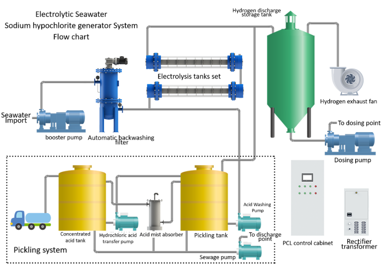
| Seawater booster pump set | The seawater booster pump set provides the power source for the seawater filter and the back-end process to overcome the pressure drop. |
| Sea water filtration system |
Filter seawater to micron level to prevent large particles from entering the electrolytic cell group and affecting the electrolysis process. |
|
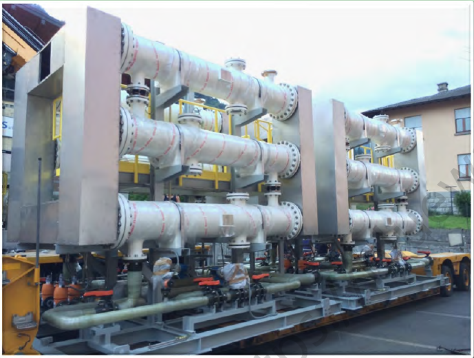
Electrolyzer group |
The electrolytic cell group is the core unit of the whole set of equipment. The electrolytic cell group adopts titanium-based ruthenium and iridium rare metal oxide coating. The seawater passes through the electrolytic cell group through direct current catalysis to convert seawater’s sodium chloride into sodium hypochlorite and hydrogen. |
| Rectifier transformer |
Usually a rectifier transformer in the form of a silicon controlled rectifier is used, the voltage is changed to the required voltage through the transformer, and then a thyristor is used for controlled rectification. The input AC power is converted into DC power and the positive and negative poles provide power source and output to the electrolytic cell. |
| Storage and dehydrogenation tank | The generated sodium hypochlorite solution and hydrogen enter the storage and dehydrogenation tank through the pipeline for temporary storage and dehydrogenation process. |
| Dehydrogenation fan unit | The wind unit generally adopts the 1D+1S form, which blows a large amount of air into the storage and dehydrogenation storage tank to dilute the produced hydrogen and provides a power source to discharge the diluted hydrogen to a safe discharge point. |
| Dosing pump set | Use corrosion-resistant centrifugal pump to output to the dosing point. |
| Pickling system | The raw material is diluted with 31% hydrochloric acid and used for acid washing of the temporary storage power supply solution tank group to remove the scale of the electrolytic tank group. |
|
Control System |
The central control system of the complete set of equipment is used to control the automatic start and stop of the complete set of equipment and coordinated control with the outside. |
|
Power distribution system |
Allocate power sources for motors and related electrical drive equipment. |
| Optional accessories | The default standard configuration of PPE electrolyzer 1. Mesh type electrolyzer (MESH) 2. Concentric circular tube electrolyzer (CTE) |
| Electricity | Sea water lifts structures and kills marine life |
| Circulating water treatment | |
| Industry | Petroleum and chemical circulating water treatment |
| Index | Unit | National standard(A) | Standard |
| Power Efficiency | % | ≥75 | ≥92 |
|
DC power consumption |
kW.H / Kg.Cl2 | ≤4.5 | ≤3.4 |
| Chlorine evolution potential | V (S.C.E) | ≤1.13 | ≤1.04 |
| Anode enhanced life test | Hr. | ≥30 | ≥100 |
| Cathode service life | Y | ≥20 | Never damaged |
|
Pickling cycle |
D | 30 | ≥36 |
| Site layout size |
Consult local business personnel |
||
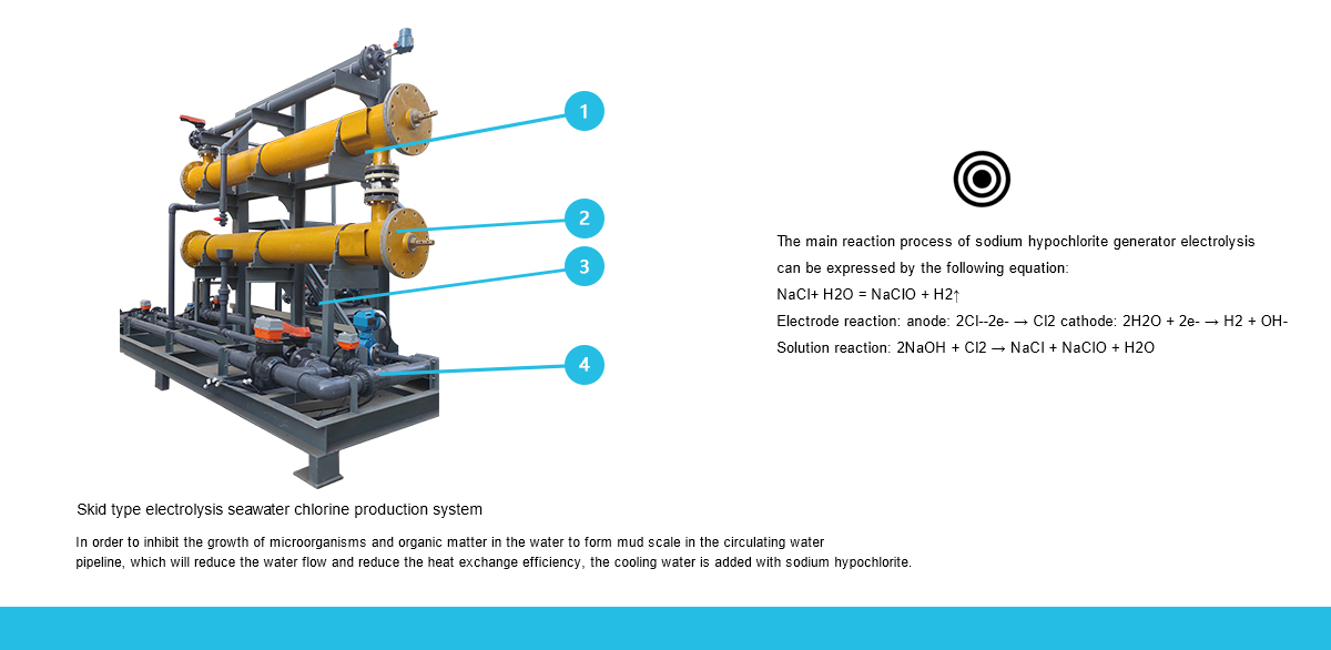
The electrolytic seawater sodium hypochlorite generator uses natural seawater and adopts high-speed electrolysis to prepare high-activity sodium hypochlorite solution on site. The sodium hypochlorite solution is transported to the dosing point as a biocide through dehydrogenation storage, effectively killing microorganisms, sea creatures, algae, and crustaceans in the water body, and preventing the blockage of circulating water pipelines and condenser systems.
The main reaction process of sodium hypochlorite generator electrolysis can be expressed by the following equation:
NaCl+ H2O = NaClO + H2↑
Electrode reaction: anode: 2Cl--2e- → Cl2 cathode: 2H2O + 2e- → H2 + OH-
Solution reaction: 2NaOH + Cl2 → NaCl + NaClO + H2O
Technical Parameters
| Model | LHB-1 | LHB-20 | LHB-50 | LHB-70 | LHB-90 | LHB-130 | LHB-220 |
| Production of available chlorine | 1KG/H | 20KG/H | 50KG/H | 70KG/H | 90KG/H | 130KG/H | 220KG/H |
| Concentration of available chlorine | 1-1.5G/L | 1-1.5G/L | 1-1.5G/L | 1-1.5G/L | 1-1.5G/L | 1-1.5G/L | 1-1.5G/L |
| Current efficiency | >80% | >80% | >80% | >80% | >80% | >80% | >80% |
| DC consumption (kwh.kg.Clz) | <4 | <4 | <4 | <4 | <4 | <4 | <4 |
| Brine consumption (kg/kg.Cl2) | - | - | - | - | - | - | - |
| Cathode lifetime(year) | 25 | ≥5 | 25 | 25 | 25 | 25 | 25 |
| External size(mm) |
1325*560*1 340 |
3800*950*1 730 |
4300*1200 *2800 |
4800*2250 *2800 |
5100*2400 *2900 |
5200*2600* 3200 |
6500*1835 *4723 |
| Area of chlorine production room | 27m2 | 216㎡2 |
270m2 - |
297m2 | 330m2 | 388m2 | 518m |
System composition:
Application areas:
Technical Parameters